Wednesday, January 23, 2013

Programming an Arduino standalone ATmega

At first I programmed my ATmega328 chips by pulling them from my circuit and placing them in one of my original Arduino boards. Something that is fun once or twice but gets really annyoing when you do it alot. So working from this tutorial I added some female headers to the circuit, dug out my trusty old SparkFun FT232RL breakout board, a 0.1uF capacitor and some jumper cables.


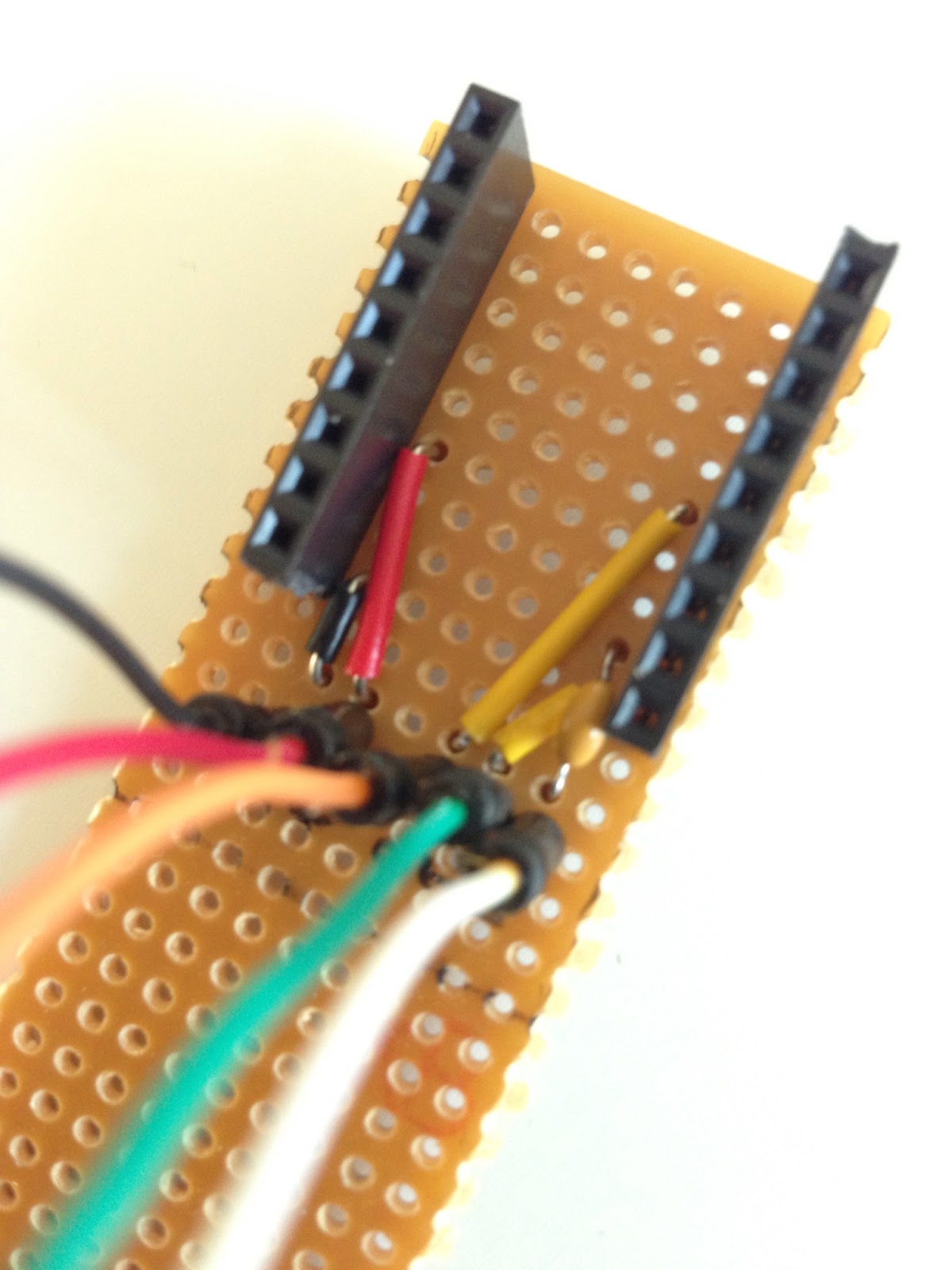
New female headers added to the RST, RX, TX, +V and GND pins.
The circular thing in the upper left corner is a RF Transmitter module. 


The Sparkfun FT232RL break out board. 

I usually placed the FT232RL break out board on a breadboard hooked up jumper cables to the corresponding pins of the ATmega. Recently I built a quick n' dirty jig with headers to hold the break out board and permanently soldered jumper cables.

You can see more pictures and read about the build here
This saves me the use of a breadboard and the tedious task of having to flip the FT232RL over numerous times to check and double check the connections.

Issues: 

avrdude: stk500_getsync(): not in sync: resp=0x1e

In Arduino IDE I used the board "Duemilanove w/ ATmega328" but kept getting the above error message. At this point I hadn't added the 0.1uF capacitor in series with the DTR pin on the FT232RL to the Reset pin on the ATmega328 so when I googled the error code and found this post it was the first thing I added. But things still wouldn't work. Until I changed my board to "Arduino Uno". After that everything worked like a charm.


FTDI shield/jig for stand alone ATmega

Made a Quick n' dirty jig to fit my Sparkfun FT232RL break out board. I found it a tad bit annoying to always having to unplug and flip board to check and double check the connectors when uploading new code to stand alone ATmega projects.

Basically it brings out the VCC, GND, RXD, TXD and DTR (via a 0.1 uF cap) pins to jumper cables. 
I'll probably add some labels later.


One end of the jumper cables permanently soldered to the jig and the other end resting in the perfboard holes.

Under the board is the pretty simple circuit with the oh so important 0.1 uF capacitor that goes between the ATmega reset pin and the FT232RL DTR pin. 


Ready and hooked up to a ATmega328P on a breadboard.

The Sparkfun FT232RL break out board.

Monday, January 21, 2013

Atari Punk Console

So I built an Atari Punk Console. It was... fun! 


Finished Atari Punk Console in a Coleman's Mustard Powder can.


Declaration of contents on the back.


Obligatory video.

I based my circuit on these two schematics. Since I only had 555 chips and not a 556 I started with the first schematic but used the 1M Ohm pots from the last one and everything after the 10 uF capacitor. I guess I just liked the sound of the 1 M Ohm pots better. I also added a powerswitch and a LED to indicate ON/OFF.


Circuit schematic found in josh1324 Instructable here.


Circuit schematic found in Collin Cunningham's Make tutorial here.


Breadboarded Circuit. This one uses 10K pots as these were the only ones I had lying around.


Halfway through mounting the circuit on a perfboard ...


... a low quality perfboard. I had alot of issues with pads coming off, well it could be my soldering technique aswell.


A green LED indicating power is on and a anarchy symbol indicating punk is on. Pretty basic ;)