I started writing the below post about a year ago but in the end I never really found a solution to the problem and consequently I never finished the post. Sometime it's best to know when to quit, but maybe this project can be of use to you anyway. Or maybe you'll find the solution that I didn't... well if you do please let me know.
Look Ma no wires!
Ok, so I've built an Arduino based Mood Light Controller and I've managed to get my Arduino to send integers over RF with VirtualWire. Finally I've also built my first Arduino Standalone ATmega / Arduino Bare.Now I've combined the three into one Wireless Arduino Mood Light Controller. To be honest I had two very different projects planned for my Standalone ATmega and the RF part but those sort of became obsolete in my current living situation.
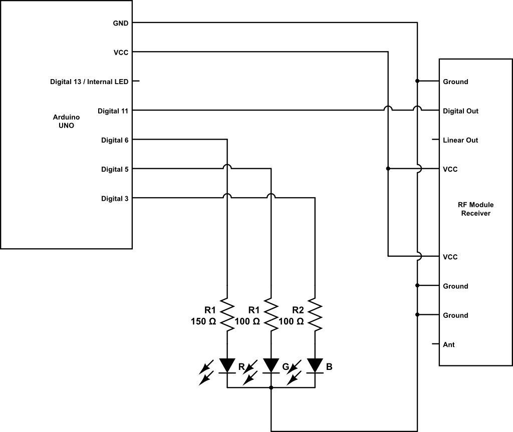 |
| Original circuit drawn with www.circuitlab.com |
 |
| Above circuit breadboarded on a protoshield. |
A bug in the code?
When I first merged the RGB Mood Light code with the RF Receiver code my Arduino kept hanging. Confident in my own coding skills I quickly aimed my blame towards those who write librarys for the Arduino IDE. The good folks in the Arduino forum managed to deflate my swelling ego and pointed out a few flaws in my code before coming to the conclusion that it might be a hardware problem."The rise and fall of a ego" is available as a thread in the Arduino forum.
Meanwhile back on earth ...
I moved my question to the General Electronics part of the Arduino forum, this time with a little more humble attitude. After following the instructions of Grumpy_Mike I quickly learned that my problems came from interference caused by using PWM to control the RGB LED. The trick was to swap out the resistors to 1K Ohm resistors in order to minimize the current and the interference it caused. With 1K Ohm resistors everything worked flawless, well except for the LED that got quite dim.
To minimize the interference Grumpy_Mike suggested the use of capacitors and/or ferrite beads. This actually helped a bit but still not good enough.
 |
| Improved circuit with capacitors to stop interference caused by PWM. |
 |
| Above circuit breadboarded on a protoshield. |
 |
| Kind of messy and lot's of wires that can cause interference. |
Apparently the problem with a circuit like this is that every lead and wire is a source of interference.So I was advised to try to make the circuit tidier, shorten leads and hope for the best.
 |
| Leads of the LED and resistors trimmed down ... |
 |
| ... and the RF receiver connected via a ferrite bead as well as an added physically distance. |
 |
| Also the power supplied to the RF receiver is decoupled with a capacitor. |
Dead end?
Unfortunately all this helped very little... and I'm sort of stuck. If you do find a solution to this please let me know as I would love to finish this project.Source code
Transmitter codeReceiver code
Please note: The above code is a work in progress and could change, stop working (worse than it already does) with out notice.
No comments:
Post a Comment